
By Kevin
PublishedDec 17, 2024in CAD

There are three 3D modeling schemes or techniques: wireframe modeling, solid modeling, and surface modeling. Each scheme serves a specific function, helping designers to implement certain designs or features. However, they use significantly different mathematical and technical approaches, introducing nuances that must be mastered. In this article, we explore CAD surface modeling and provide the key information you need to master this 3D modeling scheme. We discuss what surface modeling is, its benefits and drawbacks, where it is applied, key methods, tools, and software, as well as best practices and more.
Table of Contents
- Understanding the Basics of Surface Modeling
- What is Surface Modeling?
- History of Surface Modeling
- Applications of Surface Modeling by Industry
- 1. Manufacturing Industry
- 2. Automotive Industry
- 3. Aerospace Industry
- 4. Medical Field
- 5. AEC Industry
- Benefits of Surface Modeling
- Drawbacks of Surface Modeling
- Types of CAD Surface Modeling Methods
- 1. NURBS
- 2. Polygonal Surface Modeling
- 3. Subdivision Surface Modeling
- Key Surface Modeling Software and Tools
- Software for Surface Modeling
- Surface Modeling Creation Tools
- 1. Patch
- 2. Extrude
- 3. Revolve
- 4. Loft
- 5. Sweep
- 6. Blend
- 7. Offset
- 8. Ruled
- 9. Mirror
- 10. Planar
- 11. Radiate Surface
- Surface Modeling Editing and Refinement Tools
- 1. Redefine
- 2. Trim and Untrim
- 3. Stitch and Unstitch
- 4. Extend
- 5. Intersect
- 6. Fillet
- 7. Reverse Normal
- 8. Move, Copy and Rotate Tools
- Surface Analysis Tools
- Surface Visualization and Rendering Tools
- Best Practices for Efficient CAD Surface Modeling
- 2. Limit Surface-to-Solid-Surfaces Conversions
- 3. Add All the Requisite Features to the Surface
- 4. Keep Things Simple
- 5. Consider Adopting Hybrid Modeling
- Conclusion
Understanding the Basics of Surface Modeling
What is Surface Modeling?
Also known as free-form surface modeling, it is a 3D modeling technique that defines some or all of a 3D object’s surfaces. The surface is generally created by a set of curves that is, in turn, defined by mathematical formulae. The surfaces help accentuate and embellish solid and wireframe models by providing more details.
Designers use CAD surface modeling to depict models’ textures, smoothness, contours, and outer shapes. In fact, you can combine multiple surfaces to create a watertight object that can be converted to a solid body. You can also thicken surfaces, which ordinarily have no thickness, to form a solid. However, as explained below, you should generally avoid converting solids into surfaces unless it is necessary to repair flawed geometry in an imported model. However, you cannot split open surface models to view their internal components; splitting is only possible with solid models.
Surface modeling is generally used in conjunction with wireframe modeling or solid modeling, or, in some cases, both. For example, wireframe modeling defines the geometry of a 3D object using lines and curves. These curves and lines represent the edges of the object. On the other hand, solid modeling creates solid 3D shapes that have mass and internal components. Unlike surfaces, the boundaries of solid models have a specified thickness.
History of Surface Modeling
The development of 3D modeling was gradual, with innovations emerging to solve existing challenges. For instance, early CAD software could only represent 3D models using lines and nodes. These were known as wireframe models. However, wireframe models had gaps between the lines and nodes. This created a need: by around 1968, digital computers had already been integrated into the operation of NC machines, yet, due to the gaps, wireframe models could not be used to generate NC code for the machining of complex shapes. (See the history of CAM for a detailed discussion of the developments in CAM and CNC.)
The need to solve the deficiencies of wireframe modeling prompted the development of software capabilities to represent surfaces. As a result, computer systems for representing surfaces were developed in the 1960s. Surface models were then first used in the 1970s. Another key development occurred in the 1970s: solid modeling was introduced to represent realistic models in space. However, it was not until the 1980s that solid models were first used in 3D modeling.
Applications of Surface Modeling by Industry
CAD surface modeling is generally used to define the surfaces of 3D objects. This broad application spans multiple industries, including architecture, engineering, and construction (AEC), industrial design, medicine, and the automotive and aerospace sectors. However, examining each industry reveals subtle differences in how CAD surface modeling is applied. Here’s more on this:
1. Manufacturing Industry
Designers develop surface models during the product development stage. Freeform surface modeling allows them to create detailed digital representations of proposed products without undertaking additive manufacturing using techniques like rapid prototyping and 3D printing. It also enables them to analyze the designs in order to identify deficiencies that can be remedied way before manufacturing commences. Put simply, surface modeling promotes virtual prototyping.
2. Automotive Industry
Surface modeling is quite commonly used in the automotive industry. Designers use it to create complex curvatures of the bodies of concept cars or cars still in development.
3. Aerospace Industry
The aerospace industry was among the first to employ the NURBS surface modeling technique. Shortly after NURBS had been developed in 1979, Boeing took it up and integrated it into their TIGER CAD program. Since then, surface modeling has been a staple in this industry, with designers using it to create the complex shapes and curvatures found in aircraft.
4. Medical Field
Three-dimensional imaging data is used to create surface models. These models help practitioners and researchers to simulate and visualize the progress of diseases. In addition, the models enable professionals to understand various biomedical phenomena associated with the organ whose model they are studying.
5. AEC Industry
Professionals and companies in the AEC industry use surface modeling to create realistic representations of proposed buildings or bridges.
Benefits of Surface Modeling
Surface modeling offers the following advantages:See AlsoCS520 Assignment 4: 2D SimulatorSimulating and Verifying a 2D/3D Laser Line Sensor Measurement Algorithm on CAD Models and Real ObjectsDual-arm shaping of soft objects in 3D based on visual servoing and online FEM simulations
- CAD surface modeling makes engineering analysis easier compared to wireframe modeling
- Surface modeling simplifies the process of automatically generating CNC code, thus reducing programming and CNC machining times, which contributes to efficiency in CNC operations
- Surfaces comprehensively represent 3D models, removing the ambiguity caused by the gaps seen in wireframe models and helping designers and engineers create extremely complex and realistic shapes that would have been impossible or difficult to achieve with solid modeling
- Surface modeling is generally easier to implement than solid modeling
- This 3D modeling technique offers flexibility, i.e., the ability to manipulate the 3D models in ways that would not be possible with solid models. This advantage exists because designers do not need to define mass or thickness as they would with solid models.
- Surfaces enable you to repair imported 3D models, which may present issues when imported to new CAD environments that were not originally used to build them. For instance, you can easily delete or replace the faces of a model and then redefine the associated surfaces if such data is missing. The same cannot be said for solid models – merely deleting aspects of the model does not help you resolve missing data.
- CAD surface modeling is more beneficial than solid modeling because it lets you build out faces individually rather than requiring you to build out all the faces at once, as is the case with solid modeling.
Drawbacks of Surface Modeling
Notwithstanding the benefits listed above, CAD surface modeling has the following limitations and drawbacks:
- CAD surface modeling is generally more computationally demanding than wireframe modeling.
- Surface models are pretty difficult to edit or update once created, with designers having to delete the surface and recreate it anew.
- This 3D modeling scheme may not be appropriate for representing some geometries
- In real-world 3D modeling, surface modeling cannot be used in isolation but rather must be combined with solid modeling or wireframe modeling
- Surface models cannot be split or sliced open like solid models. This drawback arises from surface models not having mass or thickness and, therefore, being more or less hollow.
- Software that supports surface modeling may be too complex or costly for certain users, such as students.
Types of CAD Surface Modeling Methods
There are three main types of CAD surface modeling methods:
1. NURBS
Short for Non-Uniform Rational B-Spline, NURBS is an essential 3D modeling technique widely adopted in various sectors and is found in virtually every CAD modeling software. NURBS modeling is preferred in cases where designers need to create realistic and accurate digital representations of 3D objects. This is because it helps create smooth and realistic contours that can be further accentuated by adding textures. The curves in NURBS are created using splines that connect control points. For this reason, this technique differs from polygonal modeling, which uses a mesh of multiple polygons or triangles to define the surface (more on this below).
NURBS is currently the industry standard for the data exchange of geometric information. Additionally, other 3D modeling techniques, like parametric modeling, are based on the NURBS method. But as useful as NURBS is, it’s not without some drawbacks. For instance, a single NURBS surface cannot express a complex surface such as the surfaces used in human animation modeling. You need multiple surfaces for this.
2. Polygonal Surface Modeling
Also known as the polygon mesh method, polygonal surface modeling uses a collection of 2D polygons and triangles to create 3D structures. These polygons or triangles share the vertices and edges, creating a mesh.
However, this surface modeling method is less accurate and precise than other methods. Additionally, you must smooth many of the grouped polygons when using this polygon surface modeling. Failure to do this results in surfaces that feature angled protrusions rather than smooth curvatures. Still, polygon meshes help describe surfaces too complex to be described analytically (i.e., analytical description).
3D models created by scanning objects using optical or mechanical contact scanners are generally made up of polygon meshes. Another area where polygon meshes are used to define surfaces is in computer simulations – the software divides the 3D model into triangles and polygons in order to define matrix-simulation equations that calculate stress, pressure, and temperature distributions as well as deformations.
3. Subdivision Surface Modeling
Subdivision surface modeling involves subdividing a mesh severally according to a set of rules. This process increases the number of vertices of meshes in a process called densification or refinement. Essentially, the process increases the number of polygons on the model’s surface. In doing so, it allows the designer to add more details to the model and make it smoother. The image below clearly shows how subdivision can smoothen the edges of a cube. From a technical standpoint, subdivision surface modeling is much more complicated than this explanation; you can nonetheless check out the book Subdivision Surface Modeling Technology.
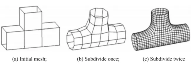
Visualization of the Subdivision Surface Modeling Process (source)
Key Surface Modeling Software and Tools
Software for Surface Modeling
There are several 3D modeling software that support surface modeling. They include Autodesk Fusion, SolidWorks, Catia, Creo, Inventor, AutoCAD, Rhino 3D, FreeCAD, Onshape, Solid Edge, and NX. Incidentally, this list includes all applications from our list of the five best parametric modeling software products and nine out of ten best 3D CAD software. This isn’t by accident, as most modern 3D CAD software supports the three schemes introduced earlier.
However, their implementation of surface modeling may vary. For example, some software applications may lack the surface modeling tools that are available in other software. You may also find that two applications use different names for a tool that serves the same function in both. The Stitch tool on Autodesk Fusion is named the Knit tool on SolidWorks, for instance. Additionally, the implementation of surface modeling in some 3D modeling software is more advanced than in others. For example, while AutoCAD does support CAD surface modeling, it is less advanced than other software like SolidWorks, Solid Edge, and Catia. It is, therefore, advisable to use powerful 3D modeling software, as it will guarantee the best possible results.
Surface Modeling Creation Tools
Each software mentioned above has a set of tools to enable you to design and analyze surfaces. It is worth pointing out that some tools may only be available in some software and not others. For instance, Creo has the blend tool, while Autodesk Fusion does not. On the other hand, Solid Edge has the BlueSurf tool, while Creo and Fusion do not. Below is a list of the surface modeling creation tools and how they support surfacing work on various CAD software.
1. Patch
The Patch tool is sometimes referred to as the Fill tool. At its core, the patch tool creates a surface that fills a gap whose boundary is defined by the model’s edges, curves, or sketches. This surface has optional edge continuity from the boundary that surrounds the gap. There are six types of patches:
- Surface patch
- Coons patch
- Bicubic patch
- Bezier patch
- B-spline patch
- Fergusson patch
The six types of patches are generally differentiated by the mathematical formulae used to define them. However, this falls beyond the scope of this article. Check out the book Computer Graphics and CAD to learn more about how these mathematical techniques handle surfaces.
2. Extrude
The Extrude tool creates an extruded surface from a 2D or 3D face. You can also extrude a surface from an existing surface or a sketched profile.
3. Revolve
The Revolve CAD surface modeling tool creates surfaces around a centerline. To create the surface, you must first sketch a 2D profile of the surface. You must also define the centerline around which the surface creation tool will revolve in order to define the profile.
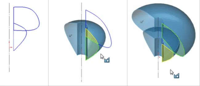
Revolved Surface in SolidWorks (source)
4. Loft
The Loft CAD surface modeling tool lets you create surfaces by first creating, through sketching, planes for the various profile sections of the loft (surface). You can also sketch the guide curves, which form the outer boundaries of the loft (as in the image below).
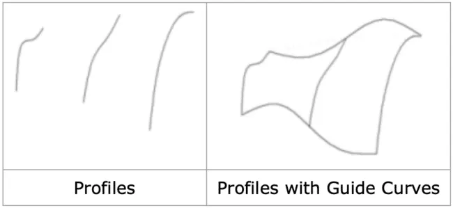
Profile-defining Planes and Guide Curves (source)
The Loft tool then creates a surface that conforms with the contours and profile defined by the sketched planes and guide curves, as shown in the image below.
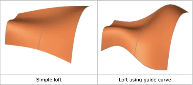
Lofted Surfaces Created Using the Loft Tool in SolidWorks (source)
5. Sweep
The Sweep tool creates a uniform surface based on the profile defined by the guide curve you sketch. It can be used with both closed and open profile sketches. The Sweep surface modeling tool creates a swept surface.
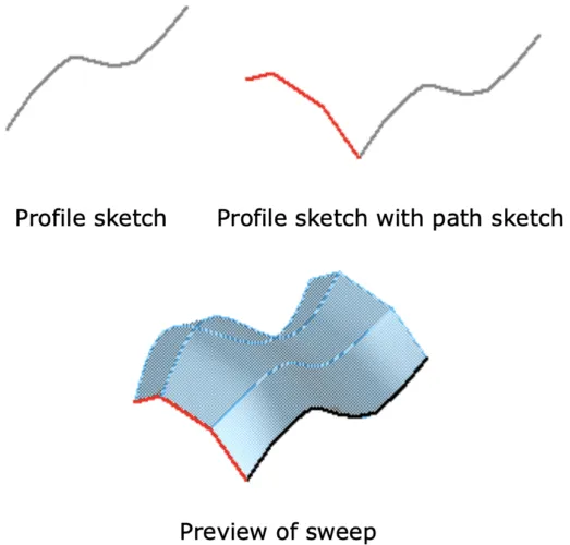
Swept Surface Created Using SolidWorks (source)
6. Blend
The Blend tool is used to connect two surfaces. It blends the junction between the surfaces, forming a smooth curvature.
7. Offset
The Offset surface modeling tool creates a new surface at a given distance from an existing surface or face.
8. Ruled
The Ruled surface modeling tool creates a surface extending along a particular plane or in a given direction. In this regard, the surface can be perpendicular or tangential to the existing face, edge, or surface.
9. Mirror
The Mirror tool creates a symmetrical replica of an existing surface by reflecting it across a plane that acts as a ‘mirror.’
10. Planar
The Planar Surface modeling tool on SolidWorks creates a flat surface. It can create planar surfaces from several closed edges, multiple lines on the same plane (coplanar lines), and a non-intersecting closed sketch.
11. Radiate Surface
The Radiate Surface tool on SolidWorks creates a surface by radiating edges of surfaces or solids along a particular, selected planar direction. Put simply, this tool offsets the edges of an existing surface or surfaces by a given dimension. Then, it creates a surface between the two edges (i.e., the inner preexisting edge and the new offset edge). This surface is parallel to the direction of the offset/plane along which the edges were offset.
Surface Modeling Editing and Refinement Tools
You can use the following CAD surface modeling editing and refinement tools:
1. Redefine
The Redefine tool on Solid Edge lets you create a single face from multiple faces that are broken up by edges. Alternatively, this tool allows you to do away with all the edges in the middle of a surface; it is helpful whenever you want the surface to feature a single continuous face.
2. Trim and Untrim
The Trim tool uses a user-specified sketch, selected surface, intersecting surfaces, or a face-cutting tool to remove an area of the surface. The Untrim tool reverses the Trim action by extending surfaces along their natural boundaries and filling gaps/holes.
3. Stitch and Unstitch
The Stitch tool joins surfaces or removes any breaks in the surfaces. This tool helps create a watertight object that can then be turned into a solid model. The Unstitch tool creates breaks in the surface. The Stitch tool is also known as Knit on SolidWorks.
4. Extend
The Extend tool is used to enlarge a surface. As its name suggests, this tool extends an existing surface by moving its edges by a specific distance.
5. Intersect
The Intersect tool on Solid Edge combines the functionalities of the Trim, Extend, and Stitch tools. It automates these tools, saving significant time.
6. Fillet
The Fillet tool creates a smooth surface. It creates curves by eliminating angled edges between two surfaces.
7. Reverse Normal
The Reverse Normal tool on Autodesk Fusion reverses or flips the positive direction of a surface. To use it, you must first select the surface whose direction you want to reverse.
8. Move, Copy and Rotate Tools
CAD software allows you to copy, move, and rotate surfaces.
Surface Analysis Tools
Surface analysis deals with the verification of the qualities of surfaces. The surface analysis tools enable you to verify that the surface meets specific requirements and geometric properties of surfaces, namely curvature, continuity, symmetry, and principal directions. Several plugins/add-on tools and dedicated tools enable you to conduct this kind of surface analysis.
For instance, Geomagic for SolidWorks lets you analyze surface deviation; it lets you compare 3D models against scanned data. Dassault Systèmes’ ICEM Surf is a geometry modeling tool for designing, analyzing, and visualizing complex free-form CAD surface models. ICEM Surf integrates with other Dassault Systèmes’ software like CATIA, 3DExcite Deltagen, the 3DExperience platform, various third-party product lifecycle management (PLM) systems available on the market, and Siemens NX.
Surface Visualization and Rendering Tools
Surface visualization and rendering relate to the appearance, texture, light, and color of the surface. Solid Edge has theReflective Plane tool, which lets you see the uncompleted half of a symmetrical model by reflecting the other half across the plane of symmetry. Solid Edge also enables you to view the bounded surface feature with the surface mesh and its associated curvature comb.
Best Practices for Efficient CAD Surface Modeling
If you are new to CAD surface modeling and are wondering what you can do to ensure that you efficiently create surfaces or master surface modeling in CAD, here are a few tips to take into account:
1. Choose the Right Software and Tools
As stated earlier, software applications ship with different surface modeling capabilities. It is, therefore, essential to select software that will handle the kind of surfaces you wish to create. At the same time, it is equally advisable to use the right tool to create a surface. Using one surface modeling tool can be tempting, yet another tool would be more suited for the task.
For instance, you may want to use the Fill tool to patch a gap, as you initially think this tool will create a surface that perfectly fits the gap. However, what you may not know is that another tool, say, the Trim tool, lets you create a surface of any size and subsequently trim/reduce its size and shape to conform to the gap. In this instance, the Trim tool would create a higher quality surface, an outcome not guaranteed with the Fill tool.
2. Limit Surface-to-Solid-Surfaces Conversions
For the best results, converting surfaces to solids only once is advisable. You should, therefore, avoid converting surfaces to solids and back to surfaces. And this is for good reason. Surface bodies are often meant to serve as intermediates as you wait to create a solid body.
However, frequent conversions, especially when working with history-based CAD software, force the software to rebuild the model frequently. Such rebuilds may take unnecessarily long, affecting your workflow and unnecessarily using up computer resources. The issue is further compounded if the model has a large number of features. But as we have stated earlier, there is an exception: you can convert solids to surfaces to repair imported data.
3. Add All the Requisite Features to the Surface
Surfaces are not mere planes or shapes that define the outward appearance of objects. So, CAD surface modeling does not stop with the creation of these surfaces. Instead, it also encompasses processes such as adding details and refining the surfaces. And as discussed earlier, 3D modeling software offers multiple solid modeling refinement tools.
4. Keep Things Simple
Avoid creating an overly complicated geometry. That means limiting the number of vertices, edges, and faces. Here are a few tips on what you can do to keep things simple:
- Do away with unwanted edges, points (vertices), or faces
- Where possible, use edges, faces, or vertices rather than curves or splines
- Do not manually draw curves if there is an existing reference, as this could affect the integrity of the resulting surface; rather, copy the reference feature whenever possible.
5. Consider Adopting Hybrid Modeling
While CAD surface modeling is a powerful tool for defining surfaces, it may not always give you the desired results. This is because this modeling scheme has a few limitations, chief among them the fact that you cannot split surfaces. For the best results, it is advisable to use multiple modeling schemes to create a 3D model in what is known as hybrid modeling.
Hybrid modeling combines two modeling schemes such as surface modeling and solid modeling. This hybrid approach enables you to create more complex 3D models than would have otherwise been possible using one scheme.
Conclusion
Surface modeling is a 3D modeling technique or scheme concerned with defining one or more surfaces of a 3D model. On the backend, 3D modeling software utilizes methods like NURBS, polygonal meshes, and subdivision surfaces to create these surfaces. However, designers do not interact with these underlying mathematical and technical methods. Instead, they use CAD surface modeling creation and refinement tools as well as analysis, visualization, and rendering tools found in the various modeling software or add-ons.
With these tools, you can create surfaces that give your 3D model a more lifelike appearance. Additionally, these tools let you implement curvatures that may not be possible using other 3D modeling techniques. But as useful as surface modeling is, it has some inherent shortcomings and should, therefore, not be used alone. For the best results, it is advisable to use surface modeling alongside solid modeling. You should also strive to keep your 3D geometry simple, choose the right tools and software, and limit solid-to-surface-to-solid conversions.
How to Create Professional CAD Drawings for Patent Applications
Best Practices for CAD Security and File Encryption